Why do they always want to do it the hard way?
—Wile E. Coyote, Genius
Imagine that Wile E. Coyote has just finished watching
"Rise of the Drones" on PBS, and he has had a
"Eureka!" moment.
He immediately dials Acme Corporation and
orders several dozen T-4 Aerial Drones. As the new manager of
Acme Corporation, you realize that
Wile E. Coyote will in all likelyhood crash
the majority of them, and you will need a good way to track warranty claims and product repairs;
as he seems to have an unlimited line-of-credit, and he has also
purchased the platinum service plan with every one of those Drones.
Manufacturing Traceability
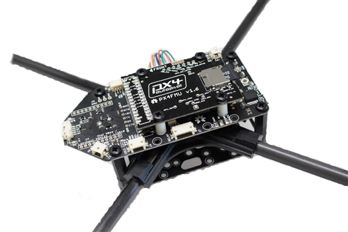
 A Drone can be a pretty complex piece of gear, with a lot of parts and subsystems.
Traceability is the ability to verify the history, location, or application
of an item by means of documented recorded identification [1].
This can be very important with components, or sensors that have a limited life time,
typically measured in hours of use. As we repair and replace crashed Drones, we'll want a way
to keep track of the major parts and subsystems, like the
Airframe,
main computer,
flight controller,
motor controllers, and the
rotors.
One of the attributes that I like about the
IPMI FRU
format for storing product information,
is it's support of manufacturing traceability properties, such as :
- product-model-name : "T-4 Aerial Drone"
- product-mfg-name : ACME Corporation
- product-mfg-date : (Univeral Time Code)
- product-mfg-loc : (GPS coordinates)
- product-asset-num : (ASSET TAG)
- product-serial-num : (SERIAL NUMBER)/(UUID)
Drone Product Tree
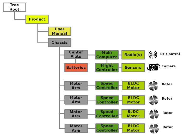
Let's take a typical quadcopter type drone design, using a central mounting plate for the batteries and main electronics, with four (4) or more motor arms to hold each of the motors and rotors. If we were to outline a simplified version of the part and subsystem heirarchy, it might look something like this :

Dynamic NFC/RFID Tags
 Now, because you are the best manager that Acme Corporation has had
in quite a while, you have decided to use a
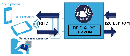
Dynamic NFC/RFID tag
at the root of your product tree, namely on the Chassis (Air Frame) itself.
This allows your service technicians to use an RFID reader/writer wand,
or their smartphone to interogate each Drone as it is tested or returned, and get the complete list of subassemblies,
their serial numbers, and dates of manufacture.
The Dynamic NFC/RFID tag can be read/written either using the RF interface, or from within the product itself - using the I2C interface to the tag. This dual interface is important, as it allows the main computer to update the Dynamic NFC/RFID tag as well.
For example, once the main computer has read all the Device Tree information from each of the different subsystems, it can update the inventory list contained within the Dynamic NFC/RFID tag. If any subsystems are changed out, the the main computer can automatically update the inventory list the next time it boots up. By designing each main subsystem to contain it's own Device Tree Overlay, the complete view of the system inventory is rebuilt each time the Drone reboots.
Why put the Dynamic NFC/RFID tag on the Airframe Chasis you ask? Well, RFID tags require a specialized antenna design to get enough range to read the tag at a distance, and the product chassis (or enclosure) will usually have suitable space to locate and mount the antenna. Besides, it is typically the "root" of the product tree, that everything else is mounted on (or in).
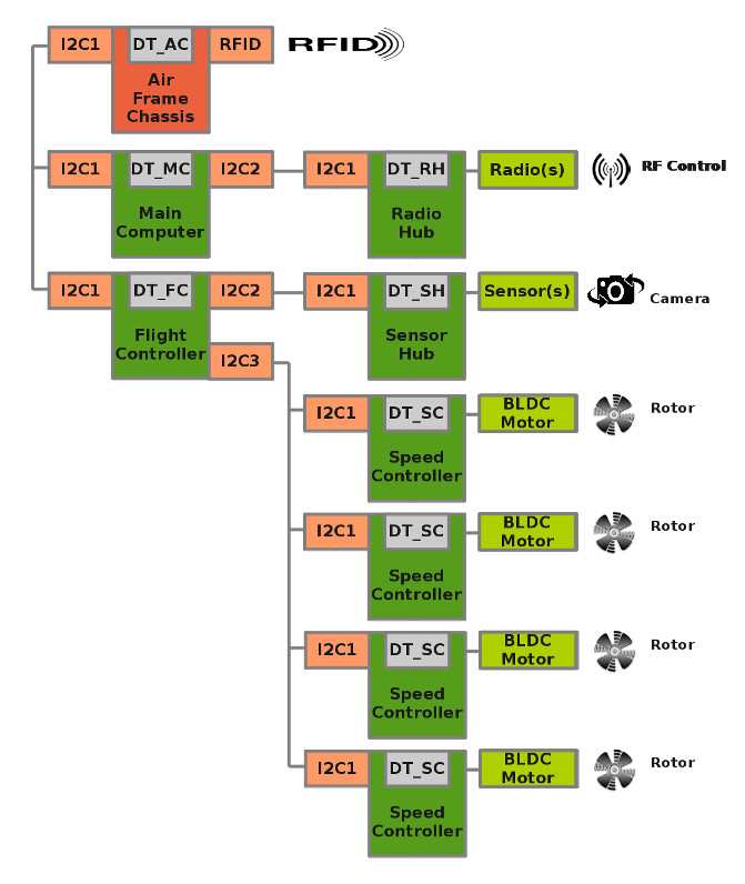
Okay, so what might that look like as we put all the subsystems together? I've diagrammed an example below, using only I2C Buses for simplicity, (a real system would have more of a mixture of I2C, SPI, and UARTs), but you get the idea...
Example Drone - Device Tree Heirarchy

Each replaceable subsystem has it's own Device Tree, for example :
- DT-MC : Main Computer (i.e. Beaglebone/RaspPi/Etc.) Device Tree
- DT-AC : Air Frame Chassis Device Tree Overlay (also accessible via RFID)
- DT-RH : Radio/RF Hub Device Tree Overlay
- DT-FC : Flight Controller Device Tree
- DT-SH : Sensor Hub Device Overlay
- DT-SC : Speed Controller#1 Device Overlay
- DT-SC : Speed Controller#2 Device Overlay
- DT-SC : Speed Controller#3 Device Overlay
- DT-SC : Speed Controller#4 Device Overlay
Product Life Cycles
Manufacturing Traceability for complex subassemblies has already been implemented using a number of technologies, including Barcode, RFid, and other methods, for many years now. Those tracking systems usually require a centralized database to store all the information required. As a board or subassembly moves from production to testing, to quality assurance, to shipping, etc., workers can read the Barcode or other identification, to register the current status of the subassembly in the centralized database. Of course, it can become difficult to employ a centralized database structure when changes are made "in the field", or across a number of different Contract Manufacturers, perhaps with incompatible internal database systems. Instead, if we put the status information into the subassembly itself, it is always present, and can be updated anywhere, at any repair depot.The Device Tree "Status" property is typically used to indicate only "on/off", that is to say, if the subassembly is enabled or disabled. It could just as easily be used to indicate phases in the life cycle, such as "untested", "QA-passed", etc. That way, incoming product returns could simply be marked, "untested" and put back into the normal factory flow for re-testing and any required rework.
By embedding the status information into the product itself, it lives and changes with the product itself, and can track the entire the product life cycle, from factory to the field, and back again, when servicing is required.
Summary
This has been a very brief introduction to the concepts behind using the the Device Tree for product life cycle tracking and management. In upcoming articles, I'll be discussing ideas for the Device Tree and Device Tree Overlays, in order to add features like calibration, Virtual I/O, and automatic interface testing.
References, Footnotes, and more Device Tree information...
- Device Tree for Dummies - Thomas Petroni
- BeagleBlack Device Tree Tutorial - Adafruit
- Xilinx Device Tree Tutorial - Xillybus
- Altera Device Tree Tutorial - Xillybus
- ARM Device Tree Support - Ubuntu
- Altera Device Tree Support - Altera
- Index of Device Tree Bindings - kernal.org
- Device Tree Graphing - kernal.org
- libfdt - manipulating FDT Blobs - David Gibson
- Linux Bootloaders - informit.com
- Device Tree PnP - Eli Billauer
- Device Tree Overlay Manager - Pantelis Antoniou
- Device Tree Overlay Proposal - Grant Likely
- BeagleBlack Univeral I/O - cdsteinkuehler
- BeagleBlack Device Tree Overlay Generator - Kilobaser
- GPIOs on the Beaglebone Black using the Device Tree Overlays- derek molloy
- Supporting 200 Different Expansion Boards - elinux.org
- DT, The Disaster so Far - Mark Rutland
- Board File to Device Tree Migration - Pantelis Antoniou
- Device Tree Overlays - Jonathon Corbet